头部背景图片

PPS PET and PA parts Cryogenic deburring/ Deflashing Machine

2024-09-27


PPS PET and PA parts nitrogen deburring machine


Cryogenic deflashing and deburring system is a process that employs cryogenic temperatures to remove flash on manufactured workpieces made of a wide range of plastics (and other materials) both thermoset and thermoplastic. Some examples of materials used include nylon, HD-PE, PPS, PET, polycarbonate, polypropylene, polyurethane, liquid crystal polymer, PA+GF, PC+GF, PEEK, and Acetal. Manufactured parts that have been successfully deburred include those made through injection molding, compression molding and extrusion molding.


 What is “Flash.”

“Flash” is a raised edge attached to the workpiece. It is an unwanted piece of material and requires removal. Many medical devices and other precision components are included in deflashing applications. Deburring accounts for a significant amount of the costs of manufacturing. The cryogenic deflashing process causes the flash or burr to become stiff or brittle and break away leaving a clean edge. There are three types of burrs that can be formed in manufacturing operations and can be classified by the physical manner of formation: Poisson burr, roll-over burr and Tear burr.

Poisson Burr

A Poisson burr results from the tendency of a material to bulge at the side when compressed until permanent deformation of the plastic occurs.

Roll-over Burr

A roll-over burr is a burr that is more of a chip that is bent rather that sheared. The resulting burr is usually comparatively larger. The process even removes recessed burrs in blind and through holes.

Tear Burr

A Tear burr is the result of material tearing from a work piece rather than shearing from it.


In the cryogenic deflashing process, parts are loaded into a basket. A cryogem such as liquid nitrogen is used to cool the workpieces. After they are cooled they are tumbled with pellets- often a polycarbonate media ranging in size from 0.006 to 0.080 inches (0.15mm to 2.03 mm.) Sometimes cryogenic deflashing does not rely on a blasting action but rather on the tumbling of the parts to remove flash from the outer edges. The process can even remove recessed burrs in blind and through holes. The process does not affect the surface finish or the geometry of the part. Edges are maintained without rounding or removal of extra material and only the unwanted burrs are removed.


Cryogenic Deflashing Systems Advantages

Cryogenic deflashing equipements provides advantages over manual deflashing.

The process maintains part integrity and critical tolerances. As it is a bath process the price per piece is far less as many more parts can be processed at the same time.

Cryogenic deflashing is non-abrasive.

As the process is computer controlled, the human operator variable is removed from the process.

Mold life is extended by the cryogenic deflashing process. Instead of making a new mold a company may choose to deburr a manufactured part cryogenically and achieve the same product quality very much as they would with a new mold for a period of time until maintenance is performed.


Pege’s Automatic Nitrogen Trimming Machine’s Features

Greater productivity

Large output in short time

Better and consistent Finish

Low Labour dependence

Space Saving

Low Media Consumption

Wide variety of rubber compounds - NR to Silicon Rubber

Low Nitrogen Usage

Simple Electrical Controls

High Efficiency Blast Wheel

Safety Interlocks

Simple and Very Low maintenance


PU TPU TPE parts cryogenic deburring machine

2024-09-27

PU TPU TPE parts cryogenic deburring machine


Cryogenic Deflashing or cryogenic deburring is available for all molded parts, including those made of plastics, polymers, nylons, rubbers, silicone rubber, polyurethane, neoprene, liquid crystal polymer, urethane, viton, polycarbonate, PTFE, PPS, delrin, polypropylene, EPDM, nitrile, butyl, DAP, ABS, PEEK, Acetal and aluminum zinc die cast and precision elastomer parts.


Cryogenic Deflashing Works On Most Molded Parts


The computer-controlled process generates repeatable and reliable results. Many medical devices and other high value precision molded components are included in our vast array of successful deflashing applications. We have processed parts manufactured through injection molding, compression molding and extrusion molding.

Our cryogenic deflashing machine offers a fast and repeatable process to remove flash from plastic parts. Through freezing, tumbling and blasting polycarbonate media at your injection molded plastic parts, we are able to remove residual mold flash time and time again.

The Cryogenic Deflashing process was originally created to remove mold flash from rubber parts. We are able to deflash rubber parts that are injection molded, extrusion molded and compression molded. We have processed parts made of various durometers. We typically deflash rubber parts made of EPDM, neoprene, Viton, Buna-N, nitrile, natural gum, SBR, butyl, and other elastomers.

Our Cryogenic Deflashing machine is often used by molders who work with silicone rubber. Silicone rubber, by its nature, is very viscous causing it to flash during the molding process. The Pege’s Deflashing machine removes mold flash from silicone rubber parts. We deflash parts made of liquid silicone rubber and even special blends of silicone rubber that include conductive fillers such as silver, graphite, nickel.


Rather than invest in an expensive new or repaired mold tool, customers can elect to extend the functional life of their mold tool by adding the additional step of deflashing, to finish the part and remove any residual flash leftover after molding operations. It is economical to pay only a slight premium per part than to invest in a new molding tool that has a limited production life.


Cryogenic Deflashing is a fast and efficient process that provides complete removal of mold flash without affecting the surface finish. Therefore, it is a safe,clean and cost-effective alternative to traditional methods.

Parts are placed in a chamber, cooled, tumbled and impacted with plastic polycarbonate media. Mold flash is removed quickly and cleanly. No dust or residue remains after deflashing.

Cryogenic Deflashing is more cost-effective than labor-intensive hand deflashing by a significant margin. The cost to process parts can range from less than .01 cent to several dollars apiece. General rule of thumb: cost is between 10% and 20% of the value of the part, although each part must be considered on its individual


Nanjing Pegedeflashing’s Cryogenic Deburring Machine’s ADVANTAGES

Greater productivity

Large output in short time

Better and consistent Finish

Low Labour dependence

Space Saving

Low Media Consumption

Wide variety of rubber compounds - NR to Silicon Rubber

Low Nitrogen Usage

Simple Electrical Controls

High Efficiency Blast Wheel

Safety Interlocks

Simple and Very Low maintenance


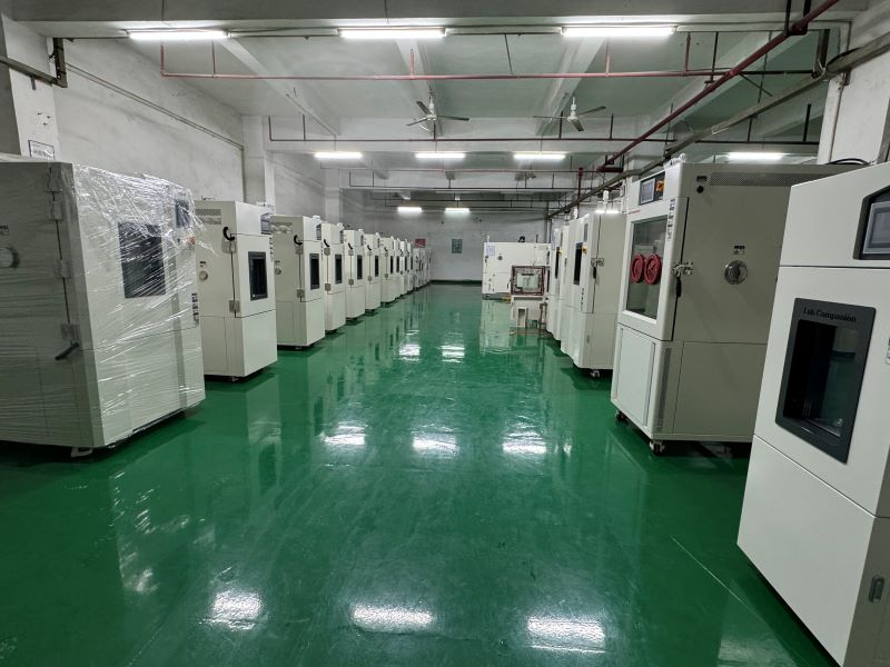
Our factory and Workshop of cryogenic deflashing systems

Nanjing Pege Techno Machine Co.,Ltd production plant is located in the No.9 Ankang road, Guli Industrial Zone, Jiangning District, Nanjing.
We have professional production workers and process, are determine to produce best product for the customer all over the world


Packing and Transportation of cryogeic deflashing equipments

The machine produced by Nanjing Pege is well packed by plywood carton suitable for long distance sea transportation to ensure machine safety and performance.

We can help customer to arrange the transportation by the terms of FOB, CIF with land or sea transportation methods according to the request from the 

The main components of an aluminum foil airline food container making machine

2024-09-27

An aluminum foil container making machine is a specialized machine used for the production of aluminum foil food containers specifically designed for use in airlines and other similar food service industries. The aluminum foil plate/ tray making machine is capable of producing a high volume of uniform and standardized food containers in a fast and efficient manner.

The main components of an aluminum foil airline food container making machine typically include:

  1. Feeding System: This system is responsible for feeding the aluminum foil material into the machine for further processing. It may consist of a roll of aluminum foil and a tension control system to ensure smooth and continuous feeding.

  2. Material Cutting System: The machine is equipped with a cutting system to accurately cut the aluminum foil into the desired shape and size for the food containers. Various cutting mechanisms such as rotary cutting or stamping may be used depending on the specific design of the machine.

  3. Molding System: This system shapes and molds the cut aluminum foil into the final form of the food container. It may utilize a combination of mechanical presses and molds to create the necessary folds and shapes required for the container.

  4. Punching System: A punching system is employed to create perforations or ventilation holes in the formed aluminum foil containers, allowing steam and heat to circulate during the food heating process.

  5. Stacking and Collection System: The machine typically includes a stacking and collection system to neatly stack and collect the finished aluminum foil containers, ready for packaging and transportation.

  6. Control System: The aluminum foil plate/ tray making machine is controlled by an automated control system that enables operators to set parameters such as container size, cutting length, perforation patterns, and production speed. It ensures proper synchronization and coordination of the various machine components for efficient operation.

The main features of an aluminum foil airline food container making machine include high production efficiency, precise cutting and shaping capabilities, adjustable container sizes, automatic operation with minimal manual intervention, and reliable performance. These machines are designed to meet the specific requirements of the airline food service industry, producing containers that are lightweight, durable, and suitable for sealing and reheating food during flight operations.

The Main Compositions of A Cryogenic Deflashing System

2024-09-27

The Main Compositions of A Cryogenic Deflashing System

A cryogenic deflashing machine, also known as a cryogenic deflashing system, is used for removing unwanted burrs, flash, or excess material from molded or machined components. The composition of a cryogenic deflashing system generally includes the following components:

1. Deflashing Chamber: This is the main working chamber where the components to be deflashed are placed. It is usually a sealed, insulated enclosure designed to withstand low temperatures.

2. Liquid Nitrogen (LN2) Supply(nitrogen deflashing machine): Cryogenic deflashing relies on liquid nitrogen as the cryogenic medium. The LN2 supply provides the necessary cooling agent required for the process.

3. LN2 Delivery System: This system is responsible for delivering liquid nitrogen to the deflashing chamber. It typically consists of supply lines, valves, and control mechanisms to regulate the flow of LN2.

4. Control Panel: The control panel houses the electrical and electronic components that control and monitor the cryogenic deflashing process. It includes temperature controllers, timers, pressure gauges, and safety features.

5. Media Circulation Mechanism: Some cryogenic deflashing machines incorporate an auto media circulation system to realize the media blasting function and then enhance the deflashing process. This can be in the form of tumbling barrels, rotating baskets, or oscillating fixtures.

6. Exhaust System: As cryogenic  deflashing process generates gases and vapors, an exhaust system is employed to remove these by-products from the deflashing chamber. It helps maintain a safe working environment and prevents the accumulation of hazardous substances.

7. Filtration System: To remove any debris or particulate matter generated during the deflashing process, a filtration system may be included. It helps ensure the cleanliness of the liquid nitrogen and prolong the equipment's lifespan.

8. Safety Features: Cryogenic deburring machines often have safety features such as emergency stop buttons, alarms, and interlocks to ensure operator safety during operation.


It's important to note that specific configurations and features of cryogenic deflashing systems may vary depending on the manufacturer and the intended application. Get more details from www.pegedeflashing.com


The Versatility and Efficiency of Mini Excavators Your Ultimate Guide

2024-09-27

Mini excavators have become increasingly popular in the construction industry due to their compact size, maneuverability, and versatility. Among the various models available, the 1.5-ton mini excavator stands out as a highly sought-after option. With features like a zero-tail design and competitive pricing, these machines offer incredible value for both large-scale construction projects and DIY enthusiasts.

1.5-Ton Mini Excavator: Compact yet Powerful

The 1.5-ton mini excavator is a powerful machine packed into a compact design. Its size and weight make it perfect for navigating tight spaces and narrow job sites that larger excavators cannot easily access. Despite its smaller stature, it doesn’t compromise on performance and efficiency.

Digger Excavator: Unleashing Digging Potential

Equipped with a high-quality digger, this mini excavator ensures effortless excavation tasks. Whether it’s digging trenches, foundations, or even swimming pools, the digger excavator gets the job done quickly and effectively. Its precise control and reliable digging capabilities make it an indispensable tool on any construction site.

Crawler Excavator: Tackling Challenging Terrain

Thanks to its crawler tracks, the mini excavator maintains stability on various terrains. From muddy conditions to rough surfaces, this excavator offers outstanding traction, ensuring smooth operation even in the most challenging environments. Its ability to navigate uneven ground redefines the possibilities and expands project capabilities.

1500KG Hydraulic Excavator: Efficient Performance

The 1500KG hydraulic excavator packs a punch when it comes to power and performance. Its hydraulic systems provide efficient and precise operation for digging, lifting, and loading tasks. With customizable attachments available, such as buckets, breakers, and grapples, this mini excavator adapts seamlessly to different project requirements.

Zero Tail Mini Excavator: Enhanced Maneuverability

The zero-tail design of this mini excavator allows it to rotate within its own footprint, improving maneuverability in confined spaces. This feature is particularly beneficial when working in urban areas where space is limited. With the ability to perform 360° turns without worrying about the tail swing, it provides maximum productivity without any compromise.

Micro Excavator: Small Size, Big Impact

For jobs that demand utmost precision and delicate operation, the micro excavator is the perfect choice. With its compact profile and agile movements, it excels in tasks like landscaping, pipe installation, and garden renovations. Its small size ensures minimal disturbance to the surrounding environment while maintaining exceptional digging capabilities.

Hot Sale Mini Excavators: Stay Ahead of the Game

In recent years, mini excavators have gained significant popularity in the construction market. Their versatility, cost-effectiveness, and efficiency make them an attractive investment. With hot sale mini excavators, you’re not only getting a reliable machine but also keeping up with current trends and advancements in construction technology.

Unleash Your Project Potential Today!

Whether you’re a contractor looking to expand your fleet or a homeowner planning a DIY project, the 1.5-ton mini excavator is a game-changer. Its compact size, powerful performance, and competitive pricing make it a valuable addition to any construction arsenal. With its zero tail design, versatility, and an array of customizable attachments, this excavator ensures that no job is too challenging.

Invest in a mini excavator today and experience the efficiency, versatility, and productivity it brings to your projects. Unleash your project potential and conquer every digging task with ease!

Application of Thermal Shock Test Chamber

2024-09-25

Application of Thermal Shock Test Chamber

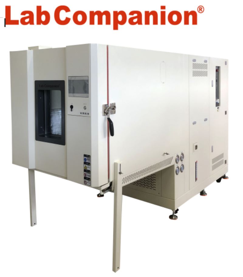
Thermal shock test chamber is an indispensable test equipment for aviation, automotive, home appliances, scientific research and other fields, used to test and determine the parameters and performance of electrical, electronic and other products and materials after temperature environment changes in high temperature, low temperature, alternating humidity and heat degree or constant test; Or constant humid heat test after the temperature environment changes the parameters and performance. Applicable to schools, factories, research positions, etc.

Thermal Shock Test Chamber

1, the high and low temperature impact test chamber with automatic, high-precision system loop, any part action, fully PLC locking processing, all use PID automatic calculation control, high temperature control precision, advanced scientific air circulation cycle design, make the indoor temperature uniform, avoid any dead corners; The complete protection device avoids any possible hidden dangers and ensures the long-term reliability of the equipment.

2, high and low temperature impact test chamber adopts advanced measuring device, and the controller adopts a large color LCD man-machine touch dialogue LCD man-machine interface controller, which is simple to operate, easy to learn, stable and reliable, and displays the complete system operation status, execution and setting program curve in Chinese and English. With 96 test specifications independently set, impact time 999 hours 59 minutes, cycle cycle 1~999 times can be set, can realize the automatic operation of the refrigerator, to a large extent to achieve automation, reduce the workload of the operator, can automatically start and stop working at any time.

3, The left side of the chamber has a test hole with a diameter of 50mm, which can be used for wiring test parts with external power load. Can be independently set high temperature, low temperature and cold and thermal shock three different conditions of the function, and in the implementation of cold and thermal shock conditions, you can choose two or three trough and cold flushing, hot flushing impact function, with high and low temperature testing machine function.

Comparison of Climatic Test and Environmental Test

2024-09-25

Comparison of Climatic Test and Environmental Test

Climate environment test -- constant temperature and humidity test chamber, high and low temperature test chamber, cold and hot shock test chamber, wet and heat alternating test chamber, rapid temperature change test chamber, linear temperature change test chamber, walk-in constant temperature and humidity test chamber, etc. They all involve temperature control.

High and Low Temperature Humidity Test Chamber

Because there are multiple temperature control points to choose from, the climate chamber temperature control method also has three solutions: inlet temperature control, product temperature control and "cascade" temperature control. The first two are single-point temperature control, and the third is two-parameter temperature control.

Single point temperature control method has been very mature and widely used.

Most of the early control methods were "ping-pong" switch control, commonly known as heating when it's cold and cooling when it's hot. This control mode is a feedback control mode. When the temperature of the circulating air flow is higher than the set temperature, the electromagnetic valve of refrigeration is opened to deliver cold volume to the circulating air flow and reduce the temperature of the air flow. Otherwise, the circuit switch of the heating device is switched on to directly heat the circulating air flow. Raise the temperature of the air stream. This control mode requires that the refrigeration device and heating components of the test chamber are always in a standby working state, which not only wastes a lot of energy, but also the controlled parameter (temperature) is always in an "oscillation" state, and the control accuracy is not high.

Now the single-point temperature control method is mostly changed to the universal proportional differential integral (PID) control method, which can give the controlled temperature correction according to the past change of the controlled parameter (integral control) and the change trend (differential control), which not only saves energy, but also the "oscillation" amplitude is small and the control accuracy is high.

Dual-parameter temperature control is to collect the temperature value of the air inlet of the test chamber and the temperature value near the product at the same time. The air inlet of the test chamber is very close to the installation position of the evaporator and heater in the air modulation room, and its magnitude directly reflects the air modulation result. Using this temperature value as the feedback control parameter has the advantage of quickly modulating the status parameters of the circulating air.

The temperature value near the product indicates the real temperature environmental conditions suffered by the product, which is the requirement of the environmental test specification. Using this temperature value as the parameter of feedback control can ensure the effectiveness and credibility of the temperature environmental test, so this approach takes into account the advantages of both and the requirements of the actual test. The dual-parameter temperature control strategy can be the independent "time-sharing control" of the two groups of temperature data, or the weighted two temperature values can be combined into one temperature value as a feedback control signal according to a certain weighting coefficient, and the value of the weighting coefficient is related to the size of the test chamber, the wind speed of the circulating air flow, the size of the temperature change rate, the heat output of the product work and other parameters.

Because heat transfer is a complex dynamic physical process, and is greatly affected by the atmospheric environment conditions around the test chamber, the working state of the tested sample itself, and the complexity of the structure, it is difficult to establish a perfect mathematical model for the temperature and humidity control of the test chamber. In order to improve the stability and accuracy of control, fuzzy logic control theory and method are introduced in the control of some temperature test chambers. In the control process, the thinking mode of human is simulated, and the predictive control is adopted to control the temperature and humidity space field more quickly.

Compared with the temperature, the selection of humidity measurement and control points is relatively simple. During the circulation flow of the well-regulated humid air into the high and low temperature cycle test chamber, the exchange of water molecules between the wet air and the test piece and the four walls of the test chamber is very small. As long as the temperature of the circulating air is stable, the circulating air flow from entering the test chamber to exiting the test chamber is in the process. The moisture content of wet air changes very little. Therefore, the relative humidity value of the detected air at any point of the circulating air flow field in the test box, such as the inlet, the middle stream of the flow field or the return air outlet, is basically the same. Because of this, in many test chambers that use the wet and dry bulb method to measure humidity, the wet and dry bulb sensor is installed at the return air outlet of the test chamber. Moreover, from the structural design of the test box and the convenience of maintenance in use, the wet and dry bulb sensor used for relative humidity measurement and control is placed at the return air inlet for easy installation, and also helps to regularly replace the wet bulb gauze and clean the temperature sensing head of the resistance PT100, and according to the requirements of the GJB150.9A wet heat test 6.1.3. The wind speed passing through the wet-bulb sensor should not be lower than 4.6m/s. The wet-bulb sensor with a small fan is installed at the return air outlet for easier maintenance and use.


Comparison of Natural Convection Test Chamber, Constant Temperature and Humidity Test Chamber and High Temperature Oven

2024-09-25

Comparison of Natural Convection Test Chamber, Constant Temperature and Humidity Test Chamber and High Temperature Oven

Instructions:

Home entertainment audio-visual equipment and automotive electronics are one of the key products of many manufacturers, and the product in the development process must simulate the adaptability of the product to temperature and electronic characteristics at different temperatures. However, when using a general oven or thermohumidity machine to simulate the temperature environment, either the oven or thermohumidity machine has a test area equipped with a circulating fan, so there will be wind speed problems in the test area.

During the test, the temperature uniformity is balanced by rotating the circulating fan. Although the temperature uniformity of the test area can be achieved through the wind circulation, the heat of the product to be tested will also be taken away by the circulating air, which will be significantly inconsistent with the actual product in the wind-free use environment (such as the living room, indoor).


Because of the relationship of wind circulation, the temperature difference of the product to be tested will be nearly 10℃, in order to simulate the actual use of environmental conditions, many people will misunderstand that only the test machine can produce temperature (such as: oven, constant temperature wet machine) can carry out natural convection test, in fact, this is not the case. In the specification, there are special requirements for wind speed, and a test environment without wind speed is required. Through the natural convection test equipment and software, the temperature environment without passing through the fan (natural convection) is generated, and the test integration test is performed for the temperature detection of the product under test. This solution can be used for home related electronics or real-world ambient temperature testing in confined Spaces (e.g., large LCD TVS, car cockpits, automotive electronics, laptops, desktops, game consoles, stereos). Etc.).

Unforced air circulation test specification :IEC-68-2-2, GB2423.2, GB2423.2-89 3.31 The difference between the test environment with or without wind circulation and the test of products to be tested:

Instructions:


If the product to be tested is not energized, the product to be tested will not heat itself, its heat source only absorbs the air heat in the test furnace, and if the product to be tested is energized and heated, the wind circulation in the test furnace will take away the heat of the product to be tested. Every 1 meter increase in wind speed, its heat will be reduced by about 10%. Suppose to simulate the temperature characteristics of electronic products in an indoor environment without air conditioning, if an oven or a constant temperature humidifier is used to simulate 35 ° C, although the environment can be controlled within 35 ° C through electric heating and compressor, the wind circulation of the oven and the thermohumidifier will take away the heat of the product to be tested. So that the actual temperature of the product to be tested is lower than the temperature under the real windless state, it is necessary to use a natural convection testing machine without wind speed to effectively simulate the actual windless environment (indoor, no starting car cockpit, instrument chassis, outdoor waterproof box... Such environment).

Comparison table of wind speed and IC product to be tested:

Description: When the ambient wind speed is faster, the IC surface temperature will also take away the IC surface heat due to the wind cycle, resulting in the faster the wind speed and the lower the temperature.


Definition and Characteristics of UV Weathering Test Chamber

2024-09-25

Definition and Characteristics of UV Weathering Test Chamber

    Uv weathering test chamber is a professional equipment used to simulate and evaluate the resistance of materials to ultraviolet radiation and corresponding climatic conditions. Its core function is to simulate the effect of ultraviolet light on materials in the natural environment through artificially controlled ultraviolet radiation, temperature and humidity changes, so as to conduct comprehensive and systematic tests on the durability, color stability and physical properties of materials. In recent years, with the development of science and technology and the continuous improvement of material performance requirements, the application of UV weathering test chambers has become more and more extensive, covering plastics, coatings, rubber, textiles and other fields.

UV Weathering Test Chamber

    The characteristics of the equipment are mainly reflected in its high efficiency and accuracy. First of all, the UV weathering test chamber uses a high-intensity ultraviolet lamp, which emits an ultraviolet spectrum close to sunlight, which can accurately simulate the lighting conditions in the real environment. Secondly, it has a real-time monitoring and control system, which can precisely regulate the internal temperature, humidity and UV intensity to ensure the stability of the test process and the reliability of the results. In addition, the internal material and structural design of the test chamber is also particularly important, which usually uses corrosion resistant and oxidation resistant materials to extend the service life of the equipment and improve the accuracy of the test.

    In addition, the application of UV weathering test chamber is not only limited to the aging detection of materials, but also can predict and improve the performance of materials, making manufacturers more forward-looking and scientific in material selection and product design. The use of this equipment to a large extent reduces the quality problems caused by the lack of weather resistance of the product and improves the market competitiveness of the product. Therefore, in the material research and development, the UV weathering test chamber can be described as an indispensable auxiliary tool, which helps enterprises quickly detect and optimize material properties to meet the changing needs of the market.

    In short, UV weathering test chamber, as an advanced testing technology, is leading the progress and innovation in the field of materials science. With the increasing demand for environmentally friendly materials and long-lasting products, the importance of such equipment will only become more prominent. Its scientific, reliable and efficient will help all walks of life to develop more high-quality products to cope with more unknown challenges in the future.

Solar Module Test Project

2024-09-25

Solar Module Test Project

1. solar module reliability test specification:

The reliability test of the solar module is to confirm the performance of the solar module (early), and the test specifications for the module are mainly IEC61215, IEC61646, UL1703 three test specifications. IEC61215 is suitable for crystalline (Si) modules; IEC61646 is suitable for thin-film (Thin-flm) modules; The UL1703 is suitable for both crystalline and thin film solar modules. In addition, the GB and CNS solar energy specifications are partially modified from the IEC.

2. the relationship and importance of Macro Exhibition and solar energy test projects:

According to IEC61215, IEC61646 test items a total of about 10 (solar module test items corresponding to the general table). Among them, the test equipment manufactured by Hongjian will be used, and the relevant test conditions are temperature cycling (Thermal cycling, 10.11). There are three categories of Humidity freeze (10.12) and Damp heat (10.13), while UL1703 only has two items of temperature cycle wet freezing without the item of damp heat.

3. Thermal cycling test (Thermal cycling)lEC61215-10-11:

Solar module temperature cycle test is used to determine the fatigue, thermal failure, or other stress failure caused by repeated changes in temperature of the module. The current number of temperature cycles is 200 times, and the future trend will be 600 times (according to the test results of the American Association for Renewable Energy [NREL], the power degradation rate of 600 times is greater than 200 times as much as twice).

Through the temperature cycle: defects of the module can be found: crack growth, module cracks, warping, sealing material delamination, point shedding, glass corrosion... Let's wait.

Temperature conditions: Low temperature :-40℃, high temperature :85°C(IEC), 90 °C(UL), the fastest temperature variability (average):100 °C /h, 120 °C /h, relevant measurements need to be carried out during the test (using the Qingsheng solar energy measurement system), the test process needs to measure the module: module surface temperature, voltage and current, ground continuity, insulation... Let's wait.

4. the purpose of the temperature cycle test process through bias:

Temperature cycle test process, the specification requires through bias, the purpose of the test is to make the defective Cell heat to accelerate aging and accelerate failure test purposes, so it needs to be energized above 25℃ during the temperature cycle process, the laboratory in the United States has statistics, It was found that the difference between the failure rate of the solar module with power and without power is as high as 30%, and the experimental data indicates that if there is no power, the solar module is not easy to fail in the temperature cycle environment, so when carrying out the temperature cycle test of the solar cell (Cel)& module, it needs to be matched with a special measurement system.

5. the introduction of wet freezing test lEC61215-10-12:

Description: To determine whether the component is sufficiently resistant to corrosion damage and the ability of moisture expansion to expand the material molecules, frozen moisture is the stress to determine the cause of failure. For the product to be tested, the test stress is high temperature and high humidity (85℃/85%R.H) to low temperature (-40℃ humidity 85%R.H). Maintain to 25℃), and low temperature rise to high temperature and high humidity, rather than 85℃/85%R.H./20 hours, 85℃/85%R.H./20 hours, the purpose of 85℃/85%R.H./20 hours is to let the module surrounding full of water, 20 hours dwell time is too short, is not enough for water to penetrate into the module and junction box inside.

Through wet freezing test: Module defects can be found: cracks, warping, severe corrosion, lamination of sealing materials, failure of adhesive delamination junction box & water accumulation, wet insulation **... Etc.

Test conditions: 85 ℃ / 85% R.H. (h) 20-40 ℃ (0.5 ~ 4 h), maximum heat up 100, 120 ℃ / h, and maximum temperature of 200 ° C/h.

6. Purpose of wet freezing test:

The wet freezing test method is mainly to perform two kinds of damage to the solar module in a snowy environment.

(1). High temperature and humidity (85℃/85%R.H.) drop to -4℃ before 25℃, humidity should be controlled at 85%+5% RH. The purpose of this is to simulate the high humidity sudden change before the snow.

Before the snow, the environment will show a high humidity state, and when the temperature drops to 0℃, the water gas around the module and the junction box sealant will freeze. When the water gas freezes, its volume will expand to 1.1 times of the original, and the destruction method of ice expansion after the water gas penetrates the material gap through the water gas to achieve the purpose of this test. At present, the statistical results of wet freezing have the highest damage to junction box sealant, which will cause junction box degumming and water, and the failure ratio of module is estimated at 7%.

(2). The purpose of heating up from low temperature (-40℃) and humidity (50℃/85%R.H.) is to simulate the temperature rise in the module at sunrise in a snowy climate. Although the outdoor environment is still below 0℃, the solar module will generate electricity when there is light, and because the snow is still on the module, the heat spot effect will occur in the module. The temperature inside the module will also reach 50 ° C.

7. wet heat test (Damp heat) test IEC61215-10-13:

Description: To determine the ability of the module to resist long-term moisture penetration, according to the test results of BP Solar, its 1000 hours is not enough. The actual condition is found that the time to make the module have problems needs at least 1250 hours. According to the current requirements of the specification, the wet heat test process is not powered on, but the future trend is also to be powered on (positive and reverse bias), because it can accelerate the aging and failure of solar cells.

Test conditions: 85℃/85%R.H., time :1000 hours Defects can be found through the wet and thermal test: CELL delamination EVA(delamination, discoloration, bubble formation, atomization, Browning), connection line blackening, TCO corrosion, spot corrosion, Thin-film yellow discoloration, junction box degumming off

UV Weathering Test Chamber


Tags